
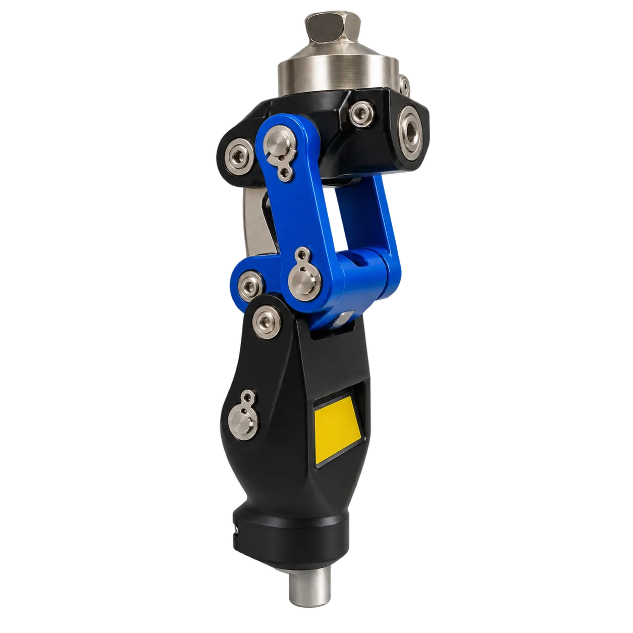
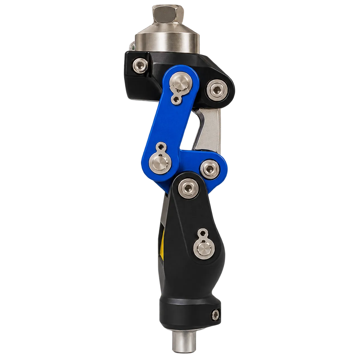
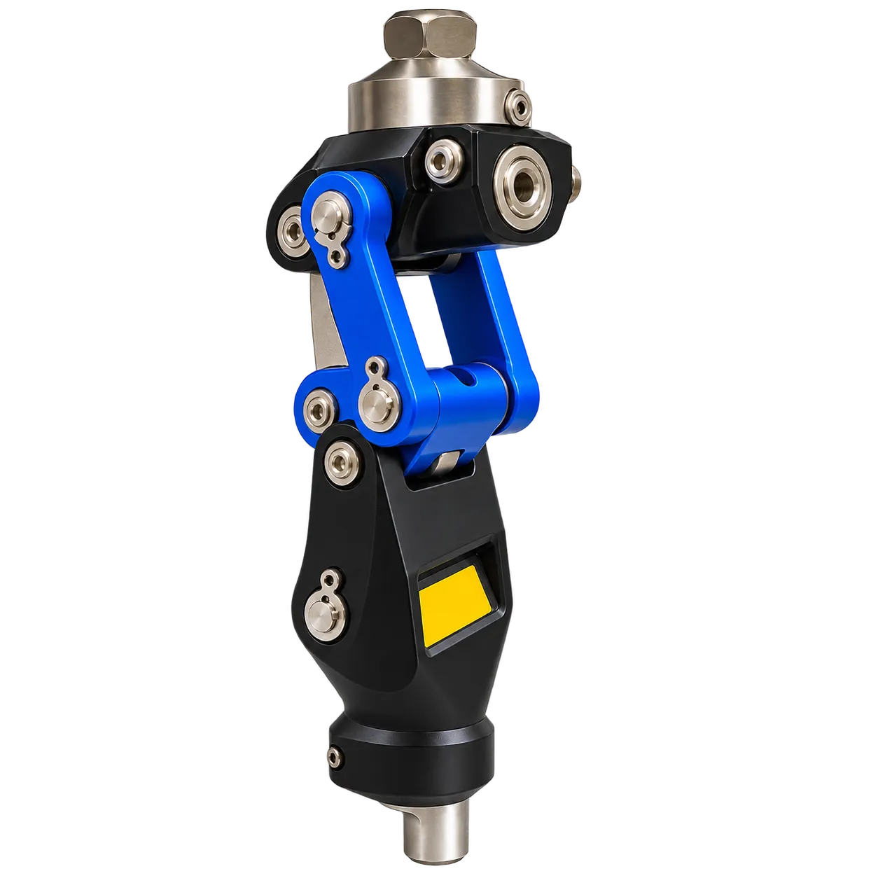
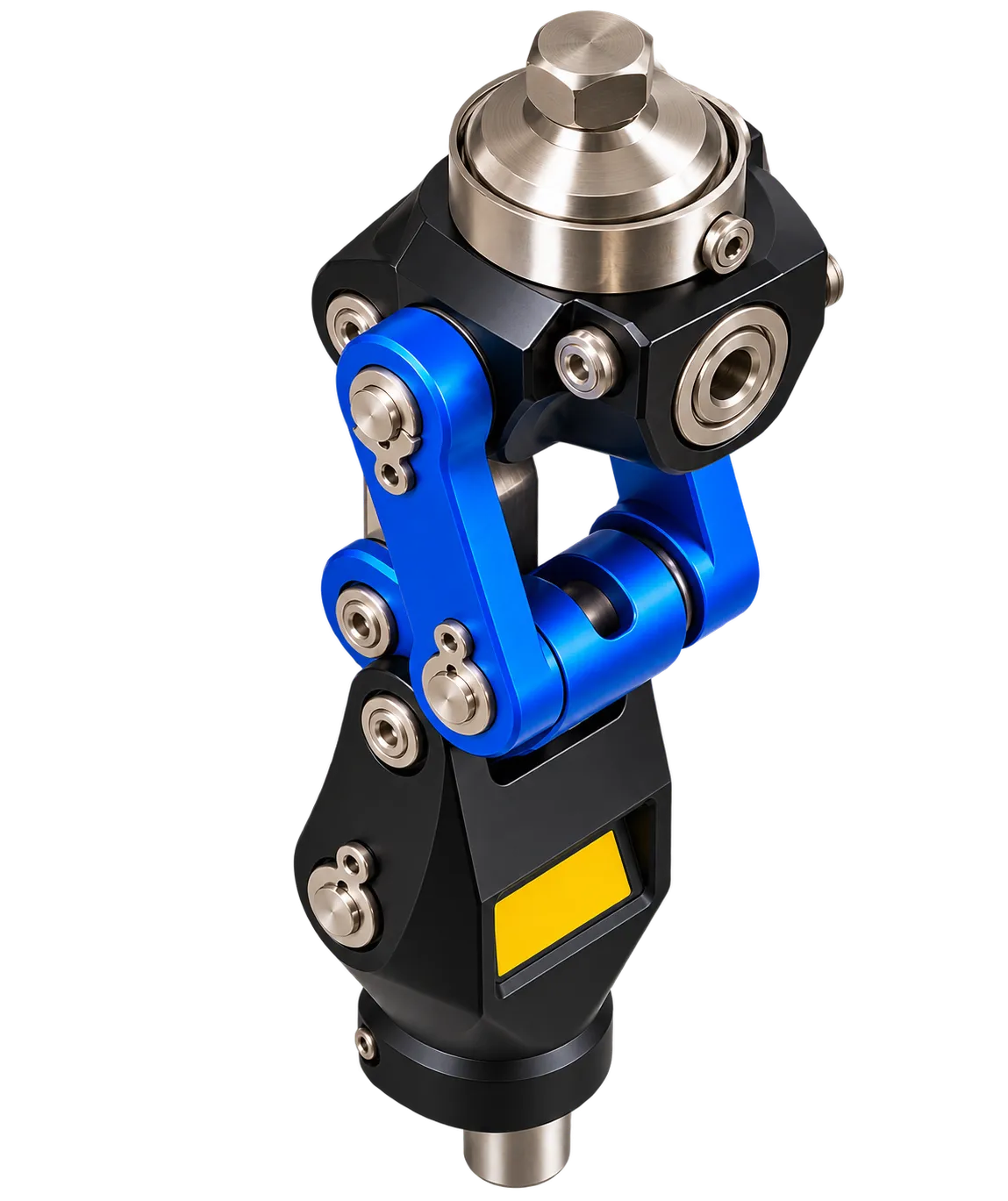
Fitting the 3FH15Z is a sequence, and a service gets the most from it by running that sequence the same way every time. It starts on the bench. The limb is assembled and stood against a plumb line, or under a laser aligner where the workshop owns one, so the load line can be placed relative to the linkage as the instructions for use direct. That placement governs the geometric lock, since the linkage holds only while the line stays ahead of the instant centre.
Next comes the baseline. The cylinder's delivered setting is written at the top of a logsheet before the wearer takes a step, and the first walk is observed with nothing altered. Adjustment then proceeds in single increments: one valve, one step, one walk, one line on the sheet. The manufacturer's handbook stays open on the bench, because increment sizes and limits are specific to this joint.
Published work explains the logic without testing this model. A 1994 paper in Prosthetics and Orthotics International described how a raised, rearward instant centre adds stability, with one linkage class holding it in the stable region for about 10° of flexion. A 1997 study of 18 below-knee amputees and 20 non-amputees found the knee centre averaging 18 mm behind the standing load line. Both are measurement and theory, and neither reports patient outcomes.
Candidates are transfemoral wearers who can load the toe to release the joint and whose limb rating covers their weight. Limb-fitting centres, private clinics and teaching workshops all suit the method. NHS trusts in England order prosthetic products through the mandated NHS Supply Chain framework, and public bodies elsewhere follow their own rules. The conformity documentation those procurement routes require is issued by the manufacturer and shared by the enquiry team.